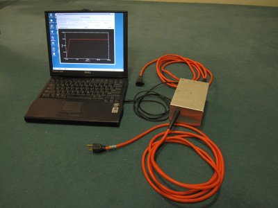
There are lots of energy consumption monitors out there, but not many of them allow you to store a nice long log of your consumption, or get at the data for further processing. Many appliances like refrigerators, dehumidifiers, etc. cycle on and off, and it's hard to know how much they are really consuming over a period of days. The best way to do this is to have a computer set up to log the data.
This monitor uses a simple electronic circuit to provide a signal for the "line in" recording input of your PC's sound card. The left and right channels record the actual AC waveforms of the voltage and current used by your appliance, allowing a true measure of power, even with inductive loads like motors. Measurements are made at intervals of your choice for as long as you like and stored in a text file for further processing.
The circuit is pretty easy to build, and the software is not too hard either. If you would like to try your hand at building one you are more than welcome to browse the details below. Enjoy!
The electronics are housed in a basic aluminum chassis box, with holes drilled on either end to allow an extension cord to pass through. There are lots of ways to put this together; I used what I had lying around for the box, and bought a basic extension cord from the local hardware store. I opted to put the box in the middle of the cord, so I could plug things in and still have some flexibility in where the computer sits. You could also put a socket on the box if you like it better that way.
NOTE:
It's important to observe safe practices when dealing with AC power! Use
a three-wire grounded extension cord and attach the green ground wire
to the chassis. Remember that black is hot and white is
neutral, and
don't mix these up. Be sure you have good strain relief where
the cord
enters the chassis. I
found some nice rubber boots and tied a knot on the inside (see photo).
I take no responsibility if you shock yourself or burn your
house down!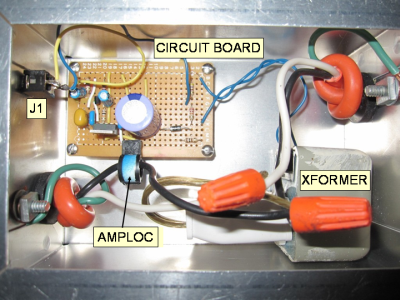
The electronic parts are mounted on a small piece of circuit board obtainiable, for example, from Radio Shack. The circuit has two sections: a simple voltage divider provides the voltage waveform, and a Hall effect current sensor (Amploc AMP25) measures the current. These sensors provide a very nice way to monitor current. You simply pass the current-carrying wire through the loop and the sensor detects the magnetic field produced by the current. They are pretty linear and easy to implement, requiring only a +5V supply. You can buy one directly from Amploc at www.amploc.com. The rest of the parts can be ordered from someplace like www.digikey.com.
Here is a pdf of the schematic and a parts list. A transformer steps the voltage down to a reasonable level to supply the divider and also power the AMP25, which needs +5V. I used an old telephone transformer that provides 13.8Vrms with 120V input. You can purchase a transformer, or scrounge anything that's small and steps the voltage down to something reasonable. A old "wall wart" could work fine, as long as it's AC. You might have to adjust the resistors in the divider if you use something different. The divider then drops this signal to about 800 mV, suitable for a line-in input. Rectifier D1, resistor R3, and capacitor C1 provide the raw DC voltage for the 7805 5V regulator. R3 limits the current during the charging of big capacitor C1. C2 and C3 clean up any high frequency spikes and C4 (tantalum) provides extra voltage stability. C2-C4 may not actually all be necessary, but they represent general good practice in making a quiet power supply. With a +5V supply the AMP25 produces a 1.55V output for -25A and a 3.45V output for +25A. 2.5V corresponds to 0A. It can supply a maximum current of 2mA. Sound cards vary in their input impedance on the line-in input. Most have about 10K and are AC-coupled, in which case the AMP25 output can be connected directly. But some are low impedance, like my laptop which has a 600-ohm input impedance. In this case the AMP25 cannot supply the necessary DC current. I added AC coupling with an emitter-follower circuit using NPN transistor Q1 to ensure sufficient current. Note any general-purpose NPN transistor should work fine here.
If your computer doesn't have a line-in input, you might be able to use the mic input, as long as it's stereo (many mic inputs are mono, however). You will of course have to play around with the signal levels, adjusting R1 and R2 in the voltage divider, and possibly attenuating the output of the AMP25.
First, I want to say that I am not a "real programmer" and my software is a bit of a hack job. But it works for me, and I supply the source code, which I encourage anyone to download and modify to their heart's content.
The code is written in C and compiled using the free GPL compiler for Windows MinGW. It makes use of the "giftware" Allegro game programming library to control the soundcard, and the "free for non-commercial use" DISLIN set of libraries for widget generation and plotting. Whatever you do with this code, be sure you are aware of the licensing agreements for these libraries. As for my code, it's free, with no strings attached, and NO WARRANTIES WHATSOEVER.
My laptop is an old dinosaur Dell Inspiron 3500 running Windows 98. I have not done a lot of testing with other systems, other than to copy the executable onto one other Windows XP system and see if it works, which it does. YMMV.
The software first sets up the Windows mixer, muting the speaker, selecting "line-in" and setting the volume. It then records three cycles of the AC waveform in each channel, and time-averages the product of the voltage and the current to calculate the true RMS power. There is a calibration routine that sets up the conversion factors based on a known load, and a data acquisition routine that logs a series of measurements.
The necessary files to run (and compile, see below) the program are in this zip file. Installation is as follows:
Create a directory where you want the program to reside, e.g. C:\Program Files\powmon
Unzip the contents of the zip file into this directory.
Using any text editor, edit the file powmoncal.dat and change the last line to reflect the default path and filename you want to use for saving your data. The zip file contains a subdirectory called "data" with a dummy file in it. You can use this, or set your default data path and filename elsewhere. You can also change the data file path and filename when running the program.

The first thing to do is to run the calibration routine calipm.exe. Open a command window, navigate to the directory, and type calipm. In this routine you choose an appropriate recording volume for the mixer and determine the conversion factors for a a true power reading. You also set the correct phase between the two channels. To do this you need a purely resistive load such as a toaster, a space heater (without fan) or even a 100 Watt bulb. Measure the actual voltage using a multimeter, and the current with a clip-on ammeter, if you have one. If you don't have a clip-on ammeter, you can cheat and divide the rated power consumption of your test load by the voltage to get an approximate RMS current. Enter these numbers in the spaces provided.
Next, connect your load to the electronics box and press "Take sample". After about 3 seconds you should see the waveforms appear (if not, see below). The maximum peak-to-peak amplitude of whichever waveform is larger should be in the range 40000 - 60000 (the sound card has a 16-bit A/D so will saturate for signals greater than 65536). If necessary, press "Change volume" to choose a volume that will give you an appropriate reading.
Then press "Adjust phase" and you should see the current waveform shift so that its peaks align with the peaks of the voltage waveform. Note the phase is measured in units of the digitizer rate, that is, 1 phase unit = 22.7 us = 1/44.1 kHz. If everything looks OK, press "Calculate new factors" , and then "Save results". The selected volume, calibration factors and phase shift will be saved in the file powmoncal.dat for use by the data logging program powmon.exe.
If
the waveforms do not show up, there is probably a problem with the
mixer setup. Mixer control is tricky, soundcard drivers vary
widely, and I have only tried a couple of computers. The program tries to detect the correct addresses for
muting the speaker, selecting "line-in", and setting the volume, but these
may fail. Some mixers enumerate the recording sources backwards.
You can try running the program with the option -rev (as in calipm -rev) to see if this fixes the problem. Alternatively, you can run it in manual mode with calipm -man. In this case the program does not try to set anything on the mixer. You have to open the Windows
mixer (for XP do the following: Settings > Control Panel > Sounds and Audio
Devices > Audio > Sound Recording > Volume), choose "line
in" and set the volume manually. Remember not to change the volume
between running calipm.exe and the logging routine, otherwise your calibration will be off. 
Once you've got the calibration factors stored, you can exit calipm and run the logging program by typing powmon (with option -rev or -man if necessary). Fill in the desired duration of the test and the interval between measurements, then press "Refresh" (don't forget this "refresh" operation; the new duration and interval won't take effect until you do it). Change the file name for the data file if you like with the "Change" button. Press "Check waveform" if you'd like to make sure an appropriate signal is being measured. When you're ready, press "START". Data will be collected and immediately written to the data file as it is acquired. Note there is no "are you sure" feature for overwriting the data file, so be careful not to overwrite data you want to keep. When the run is done the program will display the total energy consumed and the average power used. You can of course press "ABORT" whenever you like and the data acquired so far will be kept.
More likely than not you will at some point want to change, customize or adapt the software. The source code for calipm and powmon is supplied in the zip file so you can mess around with it to your hearts delight. In fact, I would be most happy to hear from someone (a real programmer perhaps?) who has improved the code or even written something better.
To compile, you will first need to obtain a C compiler such as MinGW and also install the Allegro and DISLIN libraries. If you want to learn about (and make better!) the Windows mixer control that goes on in the code, I highly recommend Alberto Dibene's tutorial. Compilation is easiest using the script clink supplied by DISLIN. Usage would be
clink -a powmon -lwinmm -lalleg
The winmm library contains the routines for controlling the mixer and is part of the MinGW distribution. alleg is the Allegro library. Note I encountered a minor conflict between Allegro and DISLIN because they both include plotting routines with the same names for primitives like "circle". To fix this I hacked the dislin.h file, making a version called mydislin.h, which is included in the zip file.
To aid in diagnosing Windows mixer issues, I have included the program scan_mixer, which runs through all the devices in the mixer and prints out info on them. Run it at a command prompt and redirect to a file for browsing with an editor: scan_mixer > scan_mixer.out.
That's about it. I hope you enjoy putting this little project together. Please send me email if you have any comments, questions, or better versions of the software that you'd like to share.
Updated January 29, 2010